How to Choose a Vertical Rock Drill in 2026?
Choosing a Vertical Rock Drill in 2026 means matching the machine to the rock, worksite, and daily production target. A drill that looks powerful on paper may perform poorly in fractured ground or cramped headings. The right choice depends on measurable details: hole diameter, drilling depth, feed force, rotation speed, air or hydraulic requirements, and available maintenance support. Small mismatches add up. A few lost minutes per hole can disrupt an entire shift.
Market reports help explain why dependable equipment matters, but they do not rank individual drills. The International Energy Agency’s Global Critical Minerals Outlook 2024 reported that lithium demand rose 30% in 2023, while demand for nickel, cobalt, graphite, and rare earths increased by 8–15%. The USGS Mineral Commodity Summaries 2025 estimated 2024 global copper mine production at about 23 million metric tons. These figures describe mineral markets, not drill performance. That distinction matters.
For buyers, the practical test is whether a Vertical Rock Drill can deliver consistent holes under the site’s actual conditions. Compare operating costs, bit compatibility, vibration, dust-control provisions, service access, and parts availability—not just purchase price. Ask suppliers for test results from similar geology, and verify the assumptions behind those results. A smooth demonstration is not a full shift. And specifications rarely tell the whole story. Even careful selection involves uncertainty; rock conditions change, and maintenance estimates can be optimistic. The sections that follow offer a grounded way to assess the trade-offs before committing to a machine.
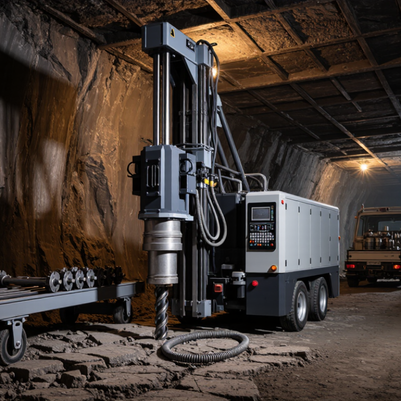
Define Hole Diameter, Depth, and Rock UCS Before Selecting a Drill
A vertical rock drill should be selected from the hole outward: diameter, depth, then rock strength. A 45 mm hole and a 100 mm hole do not impose the same bit load, flushing demand, or alignment risk. Specify the finished diameter, not just the bit size; wear can change the result. Record the deepest planned hole, too. Greater depth increases friction and makes cuttings removal more demanding. Small detail. On site, measure a few representative holes before ordering equipment. The first measurement is rarely perfect.
Rock UCS helps narrow the drill’s impact energy and feed requirements. The International Society for Rock Mechanics’ 1981 Suggested Methods classifies rock from very weak, at 1–5 MPa, through extremely strong, above 250 MPa. That range is wide. ASTM D7012 describes laboratory methods for measuring intact rock strength, but a single core result may not reflect joints, weathering, or water in the actual face. Share test results, rock type, and visible fractures with the supplier. If UCS is unavailable, label the estimate clearly rather than treating it as confirmed data. I have seen selection discussions go sideways when “hard rock” meant different things to different people. A short test hole can expose that mismatch before production starts.
Match the Drive System: Pneumatic Drills Commonly Require 0.5–0.7 MPa Air
A pneumatic vertical rock drill is only as consistent as its air supply. Many models call for 0.5–0.7 MPa, or roughly 73–102 psi, but check the specified pressure at the drill inlet while it is working. A compressor’s receiver gauge can look reassuring even when long hoses, narrow fittings, or shared air lines reduce pressure at the tool. Watch the gauge during drilling, not only before startup.
Pressure is only half the match. Confirm the drill’s required airflow and compare it with the compressor’s delivered capacity at the required pressure. The U.S. Department of Energy’s Improving Compressed Air System Performance sourcebook notes that each 2 psi increase in operating pressure can raise compressor energy use by about 1%. Higher pressure is not a free fix for a struggling line. A short, correctly sized hose and clean couplings can help limit avoidable losses.
Keep it practical. Before choosing, test the planned setup with the drill running and the same hose length used on site. If pressure falls below specification under load, expect weaker or less steady impact. Dust, altitude, and simultaneous air-tool use can complicate the result; the calculation may still miss something. That is why a field check matters.
Compare Impact Energy (J), Blow Rate (Hz), Rotation Speed (rpm), and Feed
How to Choose a Vertical Rock Drill in 2026?
Compare impact energy, blow rate, rotation speed, and feed as a working set, not four isolated numbers. Impact energy, measured in joules, describes the force of each strike; blow rate, in hertz, shows how often strikes occur. Higher values do not automatically mean faster drilling. In hard, fractured rock, excessive impact can increase vibration and bit wear. Check whether published figures were measured under load, and match them to the rock and bit size you expect to use.
Rotation speed controls how quickly the bit turns between blows. Too much speed can cause heat and wear, while too little may slow cutting. Feed is the force pressing the bit into the rock. It should keep the bit engaged without stalling rotation. A practical comparison uses the same bit diameter and similar rock conditions. Even then, the comparison is not perfectly clean: rock layers can change within a few metres. Note drilling rate, vibration, and bit condition during a short trial.
Tips: Check the drill’s operating ranges, not just peak figures. Ask how feed is adjusted, and leave room for harder sections. A tidy spec sheet helps. Field conditions still surprise you.
How to Choose a Vertical Rock Drill in 2026? — Compare Impact Energy (J), Blow Rate (Hz), Rotation Speed (rpm), and Feed
| Drill Class |
Typical Hole Diameter |
Impact Energy (J) |
Blow Rate (Hz) |
Rotation Speed (rpm) |
Feed Force (kN) |
Typical Use and Selection Notes |
| Light-duty hydraulic top hammer |
38–64 mm |
50–120 |
50–90 |
120–250 |
5–12 |
Suitable for smaller production holes and lighter rock conditions. A higher blow rate can support efficient drilling with smaller bits, provided the rock and drilling setup allow it. |
| Medium-duty hydraulic top hammer |
64–89 mm |
100–250 |
40–70 |
80–180 |
10–20 |
A balanced range for general-purpose production drilling. Match rotation speed and feed to bit diameter, rock strength, and flushing conditions to help limit wear and deviation. |
| Heavy-duty hydraulic top hammer |
89–127 mm |
200–400 |
30–60 |
50–120 |
18–35 |
Intended for larger holes and demanding rock. Higher impact energy may help with larger bits, but excessive energy or feed can increase tool wear and stress the drill string. |
| Selection check |
Use the required hole size as the starting point |
Choose enough energy for the bit and rock; more is not always better |
Consider energy per blow together with blow rate |
Set to suit bit diameter and ground conditions |
Use steady contact without overfeeding |
Check the complete drill system, including drill steel, bit, flushing capacity, rig feed, and the manufacturer’s operating limits. |
| Data note: These are indicative ranges for hydraulic top-hammer drill heads, not guaranteed specifications. Actual values vary by drill design, operating pressure, rock conditions, tooling, and measurement method. Confirm the required operating range with the equipment supplier before selection. |
Verify Compatibility Across Drill, Rod, Shank, and Bit Specifications
A vertical rock drill is only as reliable as the parts working together. Check the drill’s shank adapter against the rod connection, including thread form, diameter, and engagement length. A thread that appears to fit may still leave poor contact under impact.
Small mismatch, big trouble.
Match the rod’s diameter and length to the drill’s rated impact energy, rotation speed, and available clearance. Then confirm that the bit fits the rod and suits the rock and hole diameter. Compare the bit’s flushing passages with the drill’s air or water system; blocked or poorly aligned channels can slow cuttings removal. Use equipment drawings and operating instructions, not appearance alone.
I would not rely on a parts list that omits dimensions.
Before work, inspect threads, shoulders, and flushing holes for wear or debris. A worn shoulder can reduce energy transfer, even when the connection still assembles. Check that the complete drill, rod, shank, and bit combination is approved for the intended setup. Conditions underground can differ from a clean workshop.
That detail is easy to overlook.
Check Hand-Arm Vibration Exposure: 2.5 m/s² Action and 5 m/s² Limit
When choosing a vertical rock drill in 2026, check hand-arm vibration exposure, not just drilling speed. The 2.5 m/s² action value and 5 m/s² limit refer to daily exposure standardized over eight hours, commonly written as A(8). They are not simple readings of vibration at the handles. A drill’s stated vibration level, trigger time, and number of tasks all affect a worker’s daily exposure.
Ask for vibration data measured under relevant conditions, then compare it with the work pattern on site. For example, several short holes in hard rock may create a different exposure from continuous drilling in softer material. Record actual trigger time, and account for breaks and other vibrating tools used during the shift.
Small details matter. Worn bits, poor maintenance, and excessive grip force can make work harsher and less predictable. A neat specification sheet can still mislead; real conditions vary, and estimates have uncertainty. Check exposure regularly rather than assuming one calculation will fit every crew or job.
If estimates approach the action value, consider reducing trigger time, rotating tasks, or selecting lower-vibration equipment. Don’t treat the 5 m/s² limit as a target.